Part1组网需求
在一个新建的数据中心网络中,要求核心层具有较高的可靠性,并且希望网络结构简单,易于配置和管理。
如图1所示,根据用户需求,核心层SwitchA和SwitchB两台交换机采取堆叠组网。配置堆叠组网图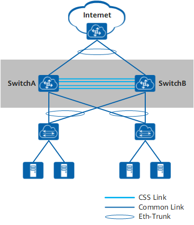
Part2配置思路
采用如下的思路配置:
1、提前规划好堆叠方案。
2、按照前期的规划,连接好SwitchA和SwitchB之间的堆叠线缆。
3、在SwitchA和SwitchB上进行堆叠软件配置,包括堆叠成员ID、堆叠优先级、堆叠域编号、堆叠端口等。
4、保存SwitchA和SwitchB的配置,并使能堆叠功能。
5、检查堆叠组建是否成功。
Part3操作步骤
1提前规划堆叠方案。
- 规划SwitchA的堆叠成员ID为1,SwitchB的成员ID为2。
- 规划SwitchA作为主交换机,其堆叠优先级最高,为150。SwitchB的堆叠优先级为100。
- 规划堆叠域编号(Domain ID)为10,不与网络中其他堆叠系统的域编号冲突。
- SwitchA和SwitchB各使用两块业务板进行堆叠转发链路的连接,用于连接的端口为10GE1/0/1~10GE1/0/2、10GE2/0/1~10GE2/0/2。
2连接堆叠线缆。
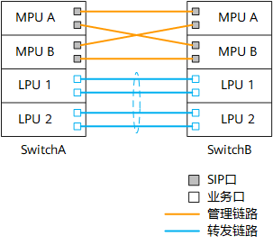
如图2所示,按照前期规划连接SwitchA和SwitchB之间的堆叠线缆。连接的端口包括主控板上的SIP口和业务板上的堆叠物理成员端口。图2 堆叠连接示意图
3配置堆叠属性。
配置SwitchA的堆叠成员ID为1,优先级为150,Domain ID为10。
<HUAWEI> system-view
[~HUAWEI] sysname SwitchA
[*HUAWEI] commit
[~SwitchA] stack
[~SwitchA-stack] stack member 1
[~SwitchA-stack] stack priority 150
Info: The operation will take effect after reboot.
[*SwitchA-stack] stack domain 10
Info: The operation takes effect only after the save command is executed. The device with a lower priority then will be reset in the stack merging scenario.
[*SwitchA-stack] quit
[*SwitchA] commit
配置SwitchB的堆叠成员ID为2,优先级为100,Domain ID为10。
<HUAWEI> system-view
[~HUAWEI] sysname SwitchB
[*HUAWEI] commit
[~SwitchB] stack
[~SwitchB-stack] stack member 2
Warning: The device will use the configuration of member ID 2 after the device resets. Continue? [Y/N]: y
[*SwitchB-stack] stack priority 100
[*SwitchB-stack] stack domain 10
Info: The operation takes effect only after the save command is executed. The device with a lower priority then will be reset in the stack merging scenario.
[*SwitchB-stack] quit
[*SwitchB] commit
4配置堆叠端口。
在SwitchA上创建堆叠端口,并将端口10GE1/0/1~10GE1/0/2、10GE2/0/1~10GE2/0/2加入堆叠端口。在SwitchB上创建堆叠端口,并将端口10GE1/0/1~10GE1/0/2、10GE2/0/1~10GE2/0/2加入堆叠端口。SwitchB的配置与SwitchA类似,配置过程略。
[~SwitchA] port-group group1
[*SwitchA-port-group-group1] group-member 10ge 1/0/1 to 10ge 1/0/2
[*SwitchA-port-group-group1] group-member 10ge 2/0/1 to 10ge 2/0/2
[*SwitchA-port-group-group1] shutdown
[*SwitchA-port-group-group1] quit
[*SwitchA] commit
[~SwitchA] interface stack-port 1
[*SwitchA-Stack-Port1] port member-group interface 10ge 1/0/1 to 1/0/2
Warning: After the configuration is complete,
1.The interface(s) (10GE1/0/1-1/0/2) will be converted to stack mode and be configured with the port crc-statistics trigger error-down command if the configuration does not exist.
2.The interface(s) may go Error-Down (crc-statistics) because there is no shutdown configuration on the interfaces.Continue? [Y/N]: y
[*SwitchA-Stack-Port1] port member-group interface 10ge 2/0/1 to 2/0/2
Warning: After the configuration is complete,
1.The interface(s) (10GE2/0/1-2/0/2) will be converted to stack mode and be configured with the port crc-statistics trigger error-down command if the configuration does not exist.
2.The interface(s) may go Error-Down (crc-statistics) because there is no shutdown configuration on the interfaces.Continue? [Y/N]: y
[*SwitchA-Stack-Port1] quit
[*SwitchA] commit
被配置为堆叠物理成员端口后,端口下会自动配置port crc-statistics trigger error-down。
待SwitchA和SwitchB上的物理端口都加入堆叠端口后,再将之前被关闭的端口打开。SwitchB的配置与SwitchA类似,配置过程略。
[~SwitchA] port-group group1
[~SwitchA-port-group-group1] undo shutdown
[*SwitchA-port-group-group1] quit
[*SwitchA] commit
[~SwitchA] quit
端口先关闭然后再打开,这样是为了避免端口因产生CRC错包而导致Error-Down。在端口Up的情况下,如果链路一端被配置为堆叠物理成员端口,另一端为普通业务口,此时端口可能会产生CRC错包。
5检查堆叠配置信息。
上述配置完成后,执行命令display stack configuration查看配置是否与规划的一致,如果不一致,需要修改配置。以查看SwitchA为例。
<SwitchA> display stack configuration
Oper          : Operation
Conf          : Configuration
MB            : MainBoard
*             : Offline configuration
Isolated Port : The port is in stack mode, but does not belong to any Stack-Port

Attribute Configuration:
---------------------------------------------------------------
 MemberID      Domain         Priority       Mode     Enable
Oper(Conf)   Oper(Conf)      Oper(Conf)   Oper(Conf)   Oper
---------------------------------------------------------------
1(1)         --(10)          100(150)     MB(MB)       Disable
---------------------------------------------------------------

Stack-Port Configuration:
--------------------------------------------------------------------------------
Stack-Port      Member Ports
--------------------------------------------------------------------------------
Stack-Port1     10GE1/0/1           10GE1/0/2           10GE2/0/1
                10GE2/0/2
--------------------------------------------------------------------------------
6保存配置并使能设备堆叠功能。
保存SwitchA的配置并使能堆叠功能。建议先使能规划为主交换机的SwitchA的堆叠功能。这样SwitchA可以先完成重启,从而优先成为主交换机。
<SwitchA> save
Warning: The current configuration will be written to the device. Continue? [Y/N]: y
<SwitchA> system-view
[~SwitchA] stack
[~SwitchA-stack] stack enable
Warning: Make sure that one or more dual-active detection methods are configured once the conversion is complete and the device enters the stack mode. Switches working in different forward modes cannot set up a CSS.
Current configuration will be converted to the next startup saved-configuration file of stack mode.
System will reboot. Continue? [Y/N]: y
使能堆叠功能后,设备会自动重启。
保存SwitchB的配置并使能堆叠功能。
<SwitchB> save
Warning: The current configuration will be written to the device. Continue? [Y/N]: y
<SwitchB> system-view
[~SwitchB] stack
[~SwitchB-stack] stack enable
Warning: Make sure that one or more dual-active detection methods are configured once the conversion is complete and the device enters the stack mode. Switches working in different forward modes cannot set up a CSS.
Current configuration will be converted to the next startup saved-configuration file of stack mode.
System will reboot. Continue? [Y/N]: y
7检查堆叠是否组建成功。
通过Console口或管理网口登录堆叠系统,使用命令display stack查看堆叠是否组建成功。当通过管理网口登录时,需要使用主交换机的IP地址。
<SwitchA> display stack
--------------------------------------------------------------------------------
MemberID Role     MAC              Priority   DeviceType         Description
--------------------------------------------------------------------------------
1        Master   006d-8835-2b00   150        CE16804
2        Standby  006d-8835-2c00   100        CE16804
--------------------------------------------------------------------------------
如上所示,显示两台交换机的信息,表示堆叠建立成功,且主交换机为成员ID为1的设备,即SwitchA。
8保存堆叠系统配置。
在检查堆叠已成功建立后,建议用户立即使用save命令保存堆叠系统配置。
<SwitchA> save
Warning: The current configuration will be written to the device. Continue? [Y/N]: y