wenmo8 发布的文章
Microsoft+Unity=3D开发新时代!
▲ Unity 选择 Azure 作为其云计算服务商和合作伙伴;两家公司将携手合作,使开发者在 Xbox 和 PC 上触达更多用户 Microsoft 坚定地致力于为创作者赋能。纵观 Windows 的历史,我们一直在培养开发者并促进他们的创造性创新。我们在 Xbox 平台上也是如此,为全球 90 多个国家的大大小小的开发者提供支持。我们的 Azure 云服务向开发者保证,他们可以释放他们的想象力,在 Azure 上构建各类安全且可扩展的应用。这是我们与长期合作伙伴 Unity—实时 3D 技术的全球领导者共有的对创作者的承诺。我们还致力于扩大 3D 内容的创建和分发,将相关工具和技术提供给更广泛的开发者,使得把游戏带给玩家变得比以往更容易。 这就是为什么今天 Unity 选择 Azure 作为其云服务商和合作伙伴,用于构建和运行 Unity 引擎的实时 3D(RT3D)体验。此外,我们很高兴能携手合作,让世界各地的游戏创作者更轻松地将游戏发布到 Xbox 游戏机和 PC 上,从而触达到这些游戏社区。 游戏中诞生的 3D 交互体验的魔力正在迅速转移到非游戏世界。Unity 正在构建一个平台中立的云原生解决方案,以满足从企业开发者到个人开发者的广泛需求。通过让创作者轻松访问 RT3D 模拟工具以及创建真实世界地点和对象的数字孪生的能力,Unity 为创作者提供了一条制作 RT3D 资产的便捷途径,无论是用于游戏还是非游戏世界。为了支持这种演变,创作者需要一个像他们一样动态和创新的技术基础设施。Azure 就是这样的解决方案。以安全和全球高扩展性为核心,Azure 已经支持了一些世界上最大的游戏,并将这些久经考验的成果为所有行业的 RT3D 体验提供支持。随着实时模拟的需求成为每个行业的核心,从电子商务到能源,从制造到医疗等等,Unity 和Microsoft 正在建立创造者专属的云,使 3D 艺术家能够在 Azure 上建立和运行这些体验。 我们在全球和各行业实现游戏和类似游戏体验的民主化开发的雄心依赖于强大的合作伙伴关系,尤其是与 Unity 等游戏引擎的合作。Microsoft 与 Unity 之间的合作伙伴关系还将使 Made with Unity 的游戏创作者能够更轻松地通过 Windows 和 Xbox 设备触达他们的玩家,并开启新的成功机会。通过定制化改进的开发人员工具、利用从芯片到云的最新平台创新以及简化游戏发布体验,Unity 创作者将能够实现他们的梦想,将他们的游戏带给全世界更多的玩家。 随着 3D 交互体验在游戏和非游戏世界中的不断发展,Microsoft 和 Unity 正在赋能一波新的创作者来定义未来的数字世界。他们的才能、创造力和同理心,不仅会改变世界,而且会让世界变得更好。
手把手教你用eNSP模拟器配置防火墙源NAT
Part1需求说明
配置PC1和PC2的IP地址
设置防火墙GE1/0/0和GE1/0/1的IP地址
将接口加入防火墙安全区域
配置域间包过滤策略
配置NAT地址池,公网地址范围2.2.2.2-2.2.2.5
配置NAT policy
验证结果,从PC1 ping PC2地址,使用display firewall session table命令查看NAT转换情况。
Part2配置过程
1配置PC1和PC2的IP地址
根据拓扑图,PC1配置如下IP地址、掩码、网关,配置完后记得点击应用:
根据拓扑图,PC2配置如下IP地址、掩码、网关,配置完后记得点击应用:
2设置防火墙GE1/0/0和GE1/0/1的IP地址
首次登陆,防火墙默认账号为admin,密码为Admin@123
进行设置防火墙的接口IP地址:
[USG6000V1]int g1/0/0

[USG6000V1-GigabitEthernet1/0/0]ip add 192.168.1.1 24

[USG6000V1-GigabitEthernet1/0/0]ip binding vpn-instance default

[USG6000V1-GigabitEthernet1/0/0]qu

[USG6000V1]

[USG6000V1]int g0/0/0

[USG6000V1-GigabitEthernet0/0/0]ip add 2.2.2.1 24

[USG6000V1-GigabitEthernet0/0/0]qu

[USG6000V1]
3将接口加入防火墙安全区域
[USG6000V1]firewall zone trust

[USG6000V1-zone-trust]add interface GigabitEthernet 1/0/0

[USG6000V1-zone-trust]add interface GigabitEthernet 0/0/0

[USG6000V1-zone-trust]
4配置域间包过滤策略
配置策略如下:
[USG6000V1]security-policy

[USG6000V1-policy-security]rule name policy-permit01

[USG6000V1-policy-security-rule-policy-permit01]source-address 192.168.1.0 24

[USG6000V1-policy-security-rule-policy-permit01]destination-address 2.2.2.0 24

[USG6000V1-policy-security-rule-policy-permit01]action permit

[USG6000V1-policy-security-rule-policy-permit01]quit

[USG6000V1-policy-security]quit

[USG6000V1]
5配置NAT地址池,公网地址范围2.2.2.2-2.2.2.5
[USG6000V1]nat address-group add-group01

[USG6000V1-address-group-add-group01]section 0 2.2.2.2 2.2.2.5

[USG6000V1-address-group-add-group01]mode pat

[USG6000V1-address-group-add-group01]qu

[USG6000V1]
6配置NAT policy
[USG6000V1]nat-policy

[USG6000V1-policy-nat]rule name nat-policy01

[USG6000V1-policy-nat-rule-nat-policy01]source-address 192.168.1.0 24

[USG6000V1-policy-nat-rule-nat-policy01]destination-address 2.2.2.0 24

[USG6000V1-policy-nat-rule-nat-policy01]action source-nat  address-group add-group01

[USG6000V1-policy-nat-rule-nat-policy01]quit

[USG6000V1-policy-nat]quit

[USG6000V1]
7验证结果
从PC1 ping PC2地址,使用display firewall session table命令查看NAT转换情况。
上图,我们可以看到192.168.1.10这个源IP地址被替换成2.2.2.4这个IP了。
接下来,我们也可以在PC1和PC2接口上抓包,观察他们的源IP地址是否有变化:
通过上图,小白们应该能对NAT源地址转换有个更清晰的认识了吧!
配置案例 | CE交换机如何配置堆叠?
在一个新建的数据中心网络中,要求核心层具有较高的可靠性,并且希望网络结构简单,易于配置和管理。 如图1所示,根据用户需求,核心层SwitchA和SwitchB两台交换机采取堆叠组网。配置堆叠组网图 采用如下的思路配置: 2、按照前期的规划,连接好SwitchA和SwitchB之间的堆叠线缆。 3、在SwitchA和SwitchB上进行堆叠软件配置,包括堆叠成员ID、堆叠优先级、堆叠域编号、堆叠端口等。 4、保存SwitchA和SwitchB的配置,并使能堆叠功能。 5、检查堆叠组建是否成功。 如图2所示,按照前期规划连接SwitchA和SwitchB之间的堆叠线缆。连接的端口包括主控板上的SIP口和业务板上的堆叠物理成员端口。图2 堆叠连接示意图 配置SwitchA的堆叠成员ID为1,优先级为150,Domain ID为10。 配置SwitchB的堆叠成员ID为2,优先级为100,Domain ID为10。 在SwitchA上创建堆叠端口,并将端口10GE1/0/1~10GE1/0/2、10GE2/0/1~10GE2/0/2加入堆叠端口。在SwitchB上创建堆叠端口,并将端口10GE1/0/1~10GE1/0/2、10GE2/0/1~10GE2/0/2加入堆叠端口。SwitchB的配置与SwitchA类似,配置过程略。 被配置为堆叠物理成员端口后,端口下会自动配置 待SwitchA和SwitchB上的物理端口都加入堆叠端口后,再将之前被关闭的端口打开。SwitchB的配置与SwitchA类似,配置过程略。 端口先关闭然后再打开,这样是为了避免端口因产生CRC错包而导致Error-Down。在端口Up的情况下,如果链路一端被配置为堆叠物理成员端口,另一端为普通业务口,此时端口可能会产生CRC错包。 上述配置完成后,执行命令 保存SwitchA的配置并使能堆叠功能。建议先使能规划为主交换机的SwitchA的堆叠功能。这样SwitchA可以先完成重启,从而优先成为主交换机。 使能堆叠功能后,设备会自动重启。 保存SwitchB的配置并使能堆叠功能。 通过Console口或管理网口登录堆叠系统,使用命令display stack查看堆叠是否组建成功。当通过管理网口登录时,需要使用主交换机的IP地址。 如上所示,显示两台交换机的信息,表示堆叠建立成功,且主交换机为成员ID为1的设备,即SwitchA。 在检查堆叠已成功建立后,建议用户立即使用save命令保存堆叠系统配置。Part1组网需求
Part2配置思路
1、提前规划好堆叠方案。Part3操作步骤
1提前规划堆叠方案。
2连接堆叠线缆。
3配置堆叠属性。
<HUAWEI> system-view
[~HUAWEI] sysname SwitchA
[*HUAWEI] commit
[~SwitchA] stack
[~SwitchA-stack] stack member 1
[~SwitchA-stack] stack priority 150
Info: The operation will take effect after reboot.
[*SwitchA-stack] stack domain 10
Info: The operation takes effect only after the save command is executed. The device with a lower priority then will be reset in the stack merging scenario.
[*SwitchA-stack] quit
[*SwitchA] commit<HUAWEI> system-view
[~HUAWEI] sysname SwitchB
[*HUAWEI] commit
[~SwitchB] stack
[~SwitchB-stack] stack member 2
Warning: The device will use the configuration of member ID 2 after the device resets. Continue? [Y/N]: y
[*SwitchB-stack] stack priority 100
[*SwitchB-stack] stack domain 10
Info: The operation takes effect only after the save command is executed. The device with a lower priority then will be reset in the stack merging scenario.
[*SwitchB-stack] quit
[*SwitchB] commit4配置堆叠端口。
[~SwitchA] port-group group1
[*SwitchA-port-group-group1] group-member 10ge 1/0/1 to 10ge 1/0/2
[*SwitchA-port-group-group1] group-member 10ge 2/0/1 to 10ge 2/0/2
[*SwitchA-port-group-group1] shutdown
[*SwitchA-port-group-group1] quit
[*SwitchA] commit
[~SwitchA] interface stack-port 1
[*SwitchA-Stack-Port1] port member-group interface 10ge 1/0/1 to 1/0/2
Warning: After the configuration is complete,
1.The interface(s) (10GE1/0/1-1/0/2) will be converted to stack mode and be configured with the port crc-statistics trigger error-down command if the configuration does not exist.
2.The interface(s) may go Error-Down (crc-statistics) because there is no shutdown configuration on the interfaces.Continue? [Y/N]: y
[*SwitchA-Stack-Port1] port member-group interface 10ge 2/0/1 to 2/0/2
Warning: After the configuration is complete,
1.The interface(s) (10GE2/0/1-2/0/2) will be converted to stack mode and be configured with the port crc-statistics trigger error-down command if the configuration does not exist.
2.The interface(s) may go Error-Down (crc-statistics) because there is no shutdown configuration on the interfaces.Continue? [Y/N]: y
[*SwitchA-Stack-Port1] quit
[*SwitchA] commitport crc-statistics trigger error-down。[~SwitchA] port-group group1
[~SwitchA-port-group-group1] undo shutdown
[*SwitchA-port-group-group1] quit
[*SwitchA] commit
[~SwitchA] quit5检查堆叠配置信息。
display stack configuration查看配置是否与规划的一致,如果不一致,需要修改配置。以查看SwitchA为例。<SwitchA> display stack configuration
Oper : Operation
Conf : Configuration
MB : MainBoard
* : Offline configuration
Isolated Port : The port is in stack mode, but does not belong to any Stack-Port
Attribute Configuration:
---------------------------------------------------------------
MemberID Domain Priority Mode Enable
Oper(Conf) Oper(Conf) Oper(Conf) Oper(Conf) Oper
---------------------------------------------------------------
1(1) --(10) 100(150) MB(MB) Disable
---------------------------------------------------------------
Stack-Port Configuration:
--------------------------------------------------------------------------------
Stack-Port Member Ports
--------------------------------------------------------------------------------
Stack-Port1 10GE1/0/1 10GE1/0/2 10GE2/0/1
10GE2/0/2
--------------------------------------------------------------------------------6保存配置并使能设备堆叠功能。
<SwitchA> save
Warning: The current configuration will be written to the device. Continue? [Y/N]: y
<SwitchA> system-view
[~SwitchA] stack
[~SwitchA-stack] stack enable
Warning: Make sure that one or more dual-active detection methods are configured once the conversion is complete and the device enters the stack mode. Switches working in different forward modes cannot set up a CSS.
Current configuration will be converted to the next startup saved-configuration file of stack mode.
System will reboot. Continue? [Y/N]: y<SwitchB> save
Warning: The current configuration will be written to the device. Continue? [Y/N]: y
<SwitchB> system-view
[~SwitchB] stack
[~SwitchB-stack] stack enable
Warning: Make sure that one or more dual-active detection methods are configured once the conversion is complete and the device enters the stack mode. Switches working in different forward modes cannot set up a CSS.
Current configuration will be converted to the next startup saved-configuration file of stack mode.
System will reboot. Continue? [Y/N]: y7检查堆叠是否组建成功。
<SwitchA> display stack
--------------------------------------------------------------------------------
MemberID Role     MAC              Priority   DeviceType         Description
--------------------------------------------------------------------------------
1        Master   006d-8835-2b00   150        CE16804
2        Standby  006d-8835-2c00   100        CE16804
--------------------------------------------------------------------------------8保存堆叠系统配置。
<SwitchA> save
Warning: The current configuration will be written to the device. Continue? [Y/N]: y
搭建Soap webservice api接口测试案例系统
Eclipse下创建WebService项目,主要目的是作为Postman、soapUI等工具进行soap webservice 接口测试的案例。
本文基于Axis2框架,在eclipse环境下搭建webservice项目,以用于后期使用SoapUI进行webservice接口测试。
1、下载Axis2框架
在官网http://axis.apache.org/axis2/java/core/download.html下载web service框架Axis2,这是Apache的一个子项目,注意下载的版本,最好和jdk版本匹配,JDK1.8需要下载1.7.x版本的。
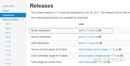
2、在eclipse中集成Axis2框架
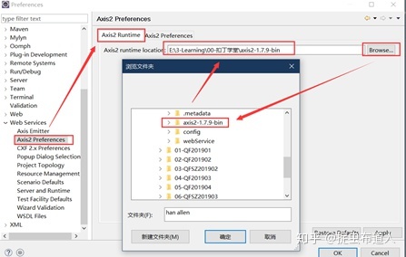
打开eclipse软件,选择一个工程目录:webservice,然后window->preferences->Web Services->Axis2 Preferences,在其中加载解压后的axis文件夹。
3、创建web项目,并提供对外访问的java类和方法
File->New->Project->web,选择Dynamic Web Project,点击下一步:
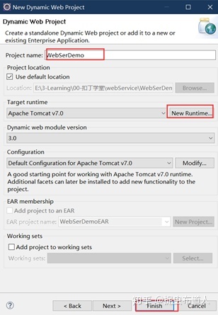
其中NewRuntime,需要配置Tomcat,如果已经安装过,只需要在此处设置安装目录即可,如果jre是1.8_xxx,选择tomcat7版本。
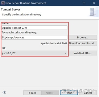
完成上面配置,直接点击Finish按钮,完成项目创建。生成的工程目录如下:
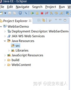
再在Java Resources->src下创建包:com.qf,在包下创建一个类:FirstDemo.java
其中实现如下类和方法的创建:
package com.qf;

import java.util.ArrayList;

public FirstDemo  {
	//创建第一个对外开放的接口方法
        //获取姓名接口
	public String getName(String name){
		if(name == null || name.equals("null") || name.equals("")){
			name = "there is no this name!!";
			return name;
		}
		System.out.println("姓名是:"+name);
		return "welcome "+name+" , to QIANFENG testing.";
	}

	//获取姓名列表接口
	public String getNameList(){
		ArrayList al = new ArrayList();
		al.add("allen");
		al.add("petter");
		al.add("Lucy");
		System.out.println(al.toString());
		return al.toString();
	}
	//获取加法运算结果接口
	public int sum(int a, int b){
		return a+b;
	}

}
4、选择项目的web service
鼠标右键New->Other->Web Service->Web Service选中,点击next。

按照下面页面进行设置,其中需要点击Browser选择刚创建的java文件,点击下一步。
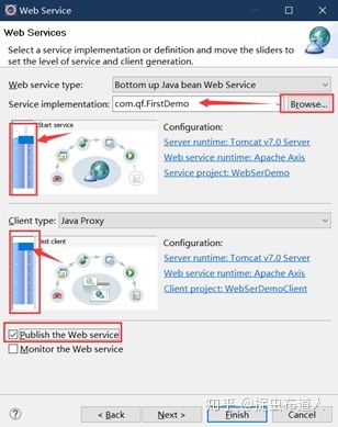
选择对外开放的接口方法,点击下一步:
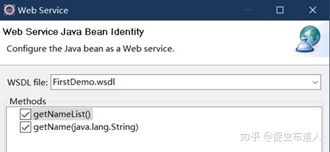
点击页面的Start server,启动Tomcat服务(注意端口问题,默认是8080端口,若有占用此端口的需要关闭其再试)
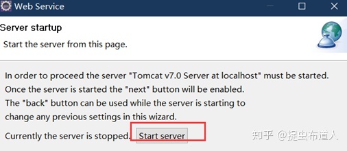
启动Tomcat服务成功后,改按钮会置灰,Eclipse控制台会显示tomcat启动日志,并处于服务状态,点击该页面的Finish完成配置。
在弹出的页面中如图设置,验证通过,则web service服务搭建成功。
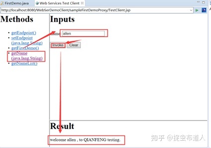
5、查看wsdl文件

通过xml文件打开,可以找到该服务提供的接口地址,末尾拼接wsdl :http://localhost:8080/WebSerDemo/services/FirstDemo?wsdl

复制该地址到浏览器中,可以查看xml格式的内容:
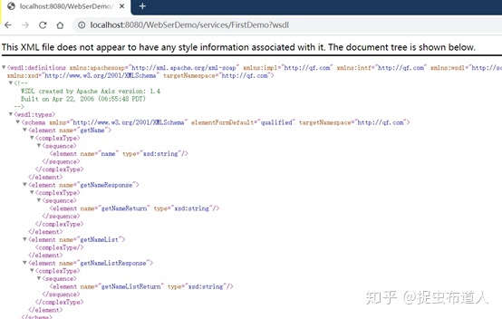
在浏览器中输入:http://localhost:8080/WebSerDemo/services,点击图示按钮,也可以打开上文的wsdl文件。
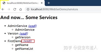
记住这个地址:http://localhost:8080/WebSerDemo/services/FirstDemo?wsdl